Okay, I ran into this issue...
When a Structural Column is located in a plan view, but the top of the column is way down this level, so it should not appear there, but it is!
However, when you look to the Element Properties of that Structural Column you will see that within the Analytical Model group the parameter "Top Vertical Projection" is set to "Top of Column". I do not know why it is set this way, but it appears to be this way sometimes...
Change this parameter to "Auto-detect". Click on OK and now your plan view looks right again.
Monday, December 15, 2008
Friday, November 28, 2008
New Web update available for Revit Architecture, Structure and MEP
To download go to this internet page for Revit Structure.
Thursday, November 27, 2008
Object Enabler for Civil 3D
I did not test it, but it seems very interesting.
Look at this Autodesk site. There you can download a Civil 3D Object Enabler. This should help you see Object information in other applications different from Civil like NavisWorks, AutoCAD, ....
Great! I will test it
Look at this Autodesk site. There you can download a Civil 3D Object Enabler. This should help you see Object information in other applications different from Civil like NavisWorks, AutoCAD, ....
Great! I will test it
Saturday, November 22, 2008
Back from the BIMstorm
It was great. With a number of 50 participants we were able to integrate models from different platforms and disciplines together into one big "Super BIM model" and next to this we were able to add Custom properties to our objects that could be shared with anyone else in the BIMcaseweek (all in Dutch).
It looks like a small step. But I think this is very important!
It looks like a small step. But I think this is very important!
Tuesday, November 11, 2008
Import SKP into Revit - units again!
When importing/linking Google Sketchup files into Revit the units can be a problem. Especially when you are working in mm in Revit...
Let's see...
The steps:
- Open Revit
- Create a Mass
- Within the Mass go to File\Import/Link\CAD Formats
- Use for Import units: Auto-detect
- Select SKP for the file type and search your Google Sketchup file
- Finish Mass
You will notice that the linked Sketchup object is too small! Although you have set the units in Google Sketchup to mm. Strange isn't it?!
- Select the Mass
- Hit the Edit button in the Option bar
- Select the Imported Sketchup object
- Go to the Element properties and you will see this.
The import units is set to inch and the scale factor to 1.000
 - Change the scale factor to 1000. Do NOT change the units
Let's see...
The steps:
- Open Revit
- Create a Mass
- Within the Mass go to File\Import/Link\CAD Formats
- Use for Import units: Auto-detect
- Select SKP for the file type and search your Google Sketchup file
- Finish Mass
You will notice that the linked Sketchup object is too small! Although you have set the units in Google Sketchup to mm. Strange isn't it?!
- Select the Mass
- Hit the Edit button in the Option bar
- Select the Imported Sketchup object
- Go to the Element properties and you will see this.
The import units is set to inch and the scale factor to 1.000
- Change the scale factor to 1000. Do NOT change the unitsThat's all!
Saturday, November 8, 2008
BIMstorm or BIMcaseweek in the Netherlands
From 17 to 21 November 2008 a BIMcaseweek is organised in the Netherlands. It is all about BIM and using different kind of applications (like Revit, NavisWorks), by different parties in one large project (buildings and infrastructure are integrated in this BIMcaseweek).
Unfortunately, the whole site is in Dutch. But keep looking to this site, it will be updated frequently in that week!
Unfortunately, the whole site is in Dutch. But keep looking to this site, it will be updated frequently in that week!
Saturday, November 1, 2008
Revit and Navisworks - the issue Shared coordinates
I ran into this problem several times. The strange thing is when you link Revit files and use Shared coordinates it all seems to work fine. Even, exporting to AutoCAD gives you the right coordinates if you set the Export options to Shared properly!
However, when exporting to NavisWorks using the NWC exporter the coordinates are handled in a strange way....
How is this possible? I figured this out...
First of all, let's start with a good Shared Coordinate Revit file (see another post of me, click here). So, in this way I am sure that it is a coorect file.
Next to this imagine the following: besides the Shared Coordinate Origin there is also a Revit Origin. And most of the times the latter give the problems!
================START==============================
To test the whole thing, I created an AutoCAD drawing with an AutoCAD block set on the WCS origin and a block put on the project location.
 I exported this using the NavisWorks exporter to a NWC file. Opened it in NavisWorks and also append the AutoCAD DWG file. They match in NavisWorks. I mean, the WCS from the AutoCAD DWG and the Revit origin from the RVT-project are on the same location. Great!

But now, I will use the method (Shared Coordinates) as descibed in a previous post.
So in Revit, the AutoCAD Project location is placed on top of the Revit origin by moving it. After that by using acquire, the right coordinates are used in Revit. After exporting this to NavisWorks the Revit origin appears on the WCS of the DWG and not on the project location!

So, there it is. When exporting to NavisWorks the export uses the Revit internal origin instead of the Shared coordinates. So, keep that in mind when you are using Revit together with other CAD-applications
However, when exporting to NavisWorks using the NWC exporter the coordinates are handled in a strange way....
How is this possible? I figured this out...
First of all, let's start with a good Shared Coordinate Revit file (see another post of me, click here). So, in this way I am sure that it is a coorect file.
Next to this imagine the following: besides the Shared Coordinate Origin there is also a Revit Origin. And most of the times the latter give the problems!
================START==============================
To test the whole thing, I created an AutoCAD drawing with an AutoCAD block set on the WCS origin and a block put on the project location.

Next I created a Revit project with an Origin family.
By using an imported AutoCAD DWG (origin-to-origin) that has on the WCS an AutoCAD Block located, I am sure about the origin location in Revit.
I exported this using the NavisWorks exporter to a NWC file. Opened it in NavisWorks and also append the AutoCAD DWG file. They match in NavisWorks. I mean, the WCS from the AutoCAD DWG and the Revit origin from the RVT-project are on the same location. Great!But now, I will use the method (Shared Coordinates) as descibed in a previous post.
So in Revit, the AutoCAD Project location is placed on top of the Revit origin by moving it. After that by using acquire, the right coordinates are used in Revit.
After exporting this to NavisWorks the Revit origin appears on the WCS of the DWG and not on the project location!So, there it is. When exporting to NavisWorks the export uses the Revit internal origin instead of the Shared coordinates. So, keep that in mind when you are using Revit together with other CAD-applications
Wednesday, October 29, 2008
Edit System Panel in Revit
Did you know that you can edit a System panel in a Curtain System within Revit ! I just figured it out. How?
First create a Curtain System using eg Massing in Revit and putting a Curtain System on it(see images).
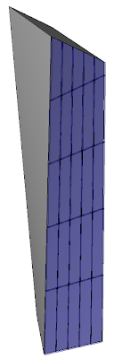
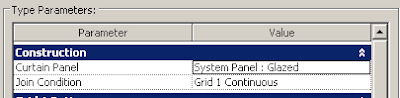
 This Curtain System uses a System Panel type Glazed
 Select the System Panel that you want to Edit and UNPIN the Panel
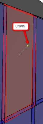 Now, you can select the Edit button in the Option bar
First create a Curtain System using eg Massing in Revit and putting a Curtain System on it(see images).
This Curtain System uses a System Panel type Glazed Select the System Panel that you want to Edit and UNPIN the PanelNow, you can select the Edit button in the Option bar Now, the Family Editor is started and you can change the System Panel.
That's all. In fact, the original System Panel is replaced by an Inplace Family
Saturday, October 25, 2008
Shared Coordinates
Working with Shared Coordinates within Revit seems strange when you are used to AutoCAD.
How, does it work?
Data set needed:
How, does it work?
Data set needed:
- First of all, you need a good DWG that uses the WCS for the coordination system.
- Next, a Revit template in which the Revit origin is obvious - I use an Origin Generic Model for that
Steps:
- Draw a Line in AutoCAD from 0,0,0 to an arbitray point close to where your project is situated
- Save that DWG and go to Revit
- Use Import/Link \ CAD format and choose your DWG
- It is important that you use the Link option, and choose the Center-to-Center option
- You will now see your DWG in your Revit View.
- If needed deselect the Crop View, in this way you will see the whole DWG after Zoom Extents
- Select the DWG and move (rotate if you want) your DWG eg using the arbitrary point to the Revit origin symbol
- Now, use Shared Coordinates \ Acquire coordinates to read out the coordinates from the DWG
- Your Revit project does use the new coordinates, you can show them by unsing Spot Dimension (do select Shared in the Type parameters of the Spot dimension, otherwise the Project coordinates are shown).

Tuesday, October 21, 2008
Freeze drawing
Today, I looked at the Freeze Drawing extension using Revit Structure 2009. This extension can be downloaded from the Autodesk site when you are a subscription member. Allways, I thought that this add-in just exported the Sheet to a DWG file and that was it. However, a closer looks gives me these results:
How it works in Revit
1. Select a View to Freeze

2. Due to some settings (see images above), the View is exported to a DWG (or not) and directly imported into an empty Drafting View.
3. When the Drafting View already exists, the naming of this Drafting View gets a version number added to it.
Pros
+ you can Freeze Multiple Views in one run
+ you can dimension non-perpendicular objects that have been cut by the view. In 3D Revit, you can not dimension non-perpendicular (to the section) objects. So, the blue walls shown in the image below can not be dimensioned without using Ref Planes (of course, I know the workaround for this)

Image 2: Normal 3D sliced walls (blue) in Revit can not be dimensioned. Workaround: Use Ref Planes
Cons
- the current DWG export settings is not sufficient to create our drawings, eg there is just one hatch layer for the wall cut patterns. A question is, do you want the View to be exported to a DWG. I think, not necessarilly. This extensions gives you the possibility to do that. However, allways a DWG is imported back into the Drafting View. And it does not look the same as in the Revit model.
- you have to re-create the Sheet.

Image 3: Resulting Drafting View
Wishes
So, I have two wishes for this Freeze Drawing extension in Revit.
1. First of all, do not use the DWG export but create the Drafting View with Detail Lines and Filled Regions.
2. Automatically change the Sheets where the View has been placed on. So, this View must be changed into the just created Drafting View.
Monday, October 20, 2008
Introduction
For months I was thinking of setting up this Blog. Now, it took some time, but here it is. What will happen here, I think about the following points:
- Creating Revit Families
- How to create intelligent parametric Revit Families
- General Tips & Tricks using Revit
- Some programming using the SDK of Revit Structure
- Integration with NavisWorks
- BIM in general, but BIMstorm or BIMcaseweek also
- Interesting Links to Plugins, Libraries, Blogs and so on...
So, I think this will be a nice and interesting Blog....
Greetings
Subscribe to:
Posts (Atom)